One of the most difficult things to do as a hobby bookbinder is to make a cover with relief (also called embossed). I made some of them and it was a tedious job whhich I never really got right. The best I ever made in the past was a bas relief like the picture shows you.
I made this by carving out the letters with a knife. Then I glued the artificial leather on the carton and pressed it in using the letters I carved out. It was minituous work and a mistake was easily made. besides that my carving isn't the best so to say the least: the result was lousy.
However time has passed on and techniques have evolved. So I just invented the best way to make a cover with relief. I am going to show you how this is easily done with a 3D printer.
The first step is to find a typeface you want to use for the job. Best way to do that is just to search free fonts with Google. Mind you a picture can be done in the same way.
In a text processor or DTP package place your text in the desired typeface as large as possible in the middle of a page with plenty room around it.
I used Open Office and the font Janda Elegant Handwriting. This font is freely available on the internet. Just search for Janda Elegant Handwriting in Google and numerous sites emerge from which you can download it freely. However there are many more usable free typefaces which you can download. Just search for 'free fonts' in Google.
Now make a screenshot from the text (or picture) in Open Office. In Windows you'll make a screenshot by pressing Control-Printscreen.
Next step is to open Paint and paste the screenshot in. Then cut out the text as tight as possible and save it under an appropriate name as a JPG file.
Now open your browser again and search for a service that converts JPG images to SVG images. An easy to use site that gives you this service is http://image.online-convert.com/convert-to-svg. Feel free to look around on this site as it offers more converters like audio and video converters. All free to use.
When the file has been converted move it to your project folder on your system.

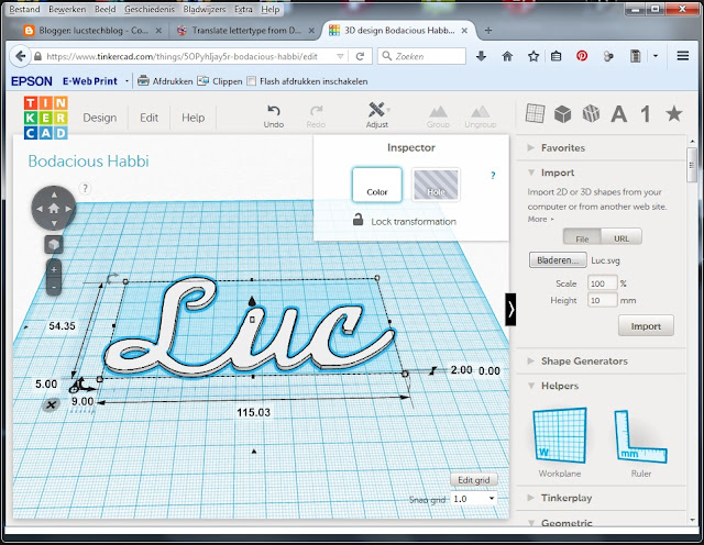
Now go to Tinkercad in your browser and open your account. Create a new design. Next choose import and import your SVG file. Now scale your subject and make sure that you adjust the height to a maximum of 2 milimeters. You can experiment with this but the hight needs to be in pace with the elasticity of the material you are going to use to make your cover with.
That's it. Now download your STL file and the first part is done.
Import the STL file in your favorite 3D printing program, slice it and print it.
Next glue the printed text or picture to the carton that is going to be your board. Let it dry 24 hours before we go to the next step.
When the text glued to the carton is completely dry put glue on the complete plate. make sure you do not forget any corners or curves because we want the leather to stick very well to the carton.
Now put the (artificial) leather on the glued surface.
Next put your pressing foam on.
And last put a pressing plate on top of that. As you can see I am using laminate as a pressing plate. The material is cheap and very strong.
Now put this hambruger in your press and press it really tight. As tight as possible. This means off course that you will not be able to use this technique without a press.
Again let this sit in your press for at least 24 hour.
And behold the fabulous result.
As said you can use this with fonts, frames and drawings. Use it on book covers, boxes, gift cards etc. Use your imagination.
As this is the last posting of this year I whish you all a very Merry Christmass and a Happy, Healthy and Inventive new Year
Until next time.
Have fun.
Luc Volders


