And guess what, it is no longer science fiction. A computer in your house that you can talk to: that's the present !!!!
And we owe it to Google. I hesitate to admit it but I love Google. Everybody is nagging at them and yet they give us so much free to use tools and gadgets. Just look at the search engine, google drive, Blogger (on which this weblog is written if you haven't noticed), the office suite, google cardboard (check into that really !!!), Android and just now Google Home Assistant.

For those of you living under a rock I will explain brief what Home Assistant is. It is the house computer from Eureka. It is Google's answer to Alexa. It is a stand alone speaker system with a build-in microphone. Indeed no screen, no keyboard, no mouse. The device is attached to the internet (be it wired or wireless) and the microphone listens to a command that activates it. The command is "OK Google" and that is something we know from Android Phones. However this is much more advanced.
There are lists with questions (easily found on the internet) you can ask Home Assistant. Examples are calculations like 535 x 345 or how many kilometres in 6 miles, or who was the first president of the United Sates, or how long is the Great Chinese Wall, or count from 10 to 25 (and backwards) or how long will it take from Rotterdam to The Hague (by car, by train or by bycicle take your pick) or will I need an umbrella tomorrow. You can also ask to roll the dice, give a random number between any two figures or flip a coin. Let it play animal sounds. You can even set alarms and timers. And a really great feature is to tell it "Remember I put my keys on tha table" and ask a few hours later where your keys are.
Basically you can ask it anything you can ask Google on your computer, and then some. And all is done by speaking out the questions and you will be answered by a pleasant womens voice. Really Amazing.
Now this wonder device will set you back at the time of this writing about 129 Dollar. But it gets better.

To get things really rolling Google supplied a Do it Yourself kit based on a Raspberry free with number 57 of the MagPi magazine. Naturally the magazine is totally sold-out.
And still better. Google gave the complete SDK free, for everyone to use.
Actually it works better as the Raspberry version. There is no button needed to activate it. Hands free commanding !!! Next to that it reacts better to questions being split up in multiple frases, and it has a timer and alarm function.
So get your Raspberry Pi out. Buy a USB microphone or use a USB audio adapter, a speaker and an SD card and build yourself a Google Home Assistant for just a few Dollar. Just follow the instructions here:
https://developers.google.com/assistant/sdk/prototype/getting-started-pi-python/
I have to admit I have wasted hours of my time just asking it silly questions. And there are many pages on the internet dedicated to publishing all the questions you can ask. Just look at this sample:
http://notsealed.com/hey-google-home-voice-commands-easter-eggs.html
At this moment there are just a few tens of millions of the original devices sold only in the US and UK as it's only language at this moment is English.
Imagine the impact this will have on society. Just think of the possibillities for disabled persons. Just command the device to set the lights on, the temperature at a certain degree, de radio at your favorite broadcaster.
Now think what we as tinkerers/hackers can do with such a device in our home. We will make our complete home automation voice commanded.
IFTTT compatibility.
You can have your Google Home (including the Raspberry DIY unit) paired with IFTTT. And then suddenly a wealth of possibillities rises.
Command your Philips Hue lights, send a tweet by voice (works flawless believe me), control your Nest thermostat, control your TV with Chromecast, keep a list of notes etc. etc. etc.
And best of all: we can control our ESP-8266 with the Google Home Assistant through IFTTT.
And that is what this entry is going to show you.
Google Home ==> IFTTT ==> ESP8266
Requirements
To get this working we need to do several steps which I discuss into detail step by step.
- Install ESP-Basic on a NodeMcu or Wemos-D1
- Set up your ESP-8266 with some leds
- Program The ESP with a Basic Program.
- Open a communication port on your router
- Get a IFTTT account (if you do not have it already)
- Set up a few IFTTT recipes
- Command your ESP by voice.
Install ESP-Basic on a NodeMcu or Wemos-D1
Well I am not going to discuss that in detail here as I have already done that in a previous story on this weblog which you can re-read here.
http://lucstechblog.blogspot.nl/2017/03/back-to-basic-basic-language-on-esp8266.html
Set up your ESP-8266 with some leds
I am using leds for demonstration purposes. But as you have seen before on this weblog you can exchange the leds for relays like in this story http://lucstechblog.blogspot.nl/2016/09/esp-relayserver.html or by transistors for controlling led-strips, pumps, motors etc. like in this story
http://lucstechblog.blogspot.nl/2016/05/esp8266-controlled-ledstrip.html.
In this setup I am attaching 6 leds which all will be individually controlled. But as you will see in the next parts of this story you can expand this easily or use a less amount easily.
The setup is very simple.

At 6 of the NodeMcu's I/O ports (D1, D2, D3, D5, D6 and D7) is a led attached through a delimiting resistor of 1K. The breadboard layout shows it all.
Program The ESP with a Basic Program.
The program is as said before written in ESP-Basic which is a fast and easy devellopping platform for all your ESP projects. It will even work on a ESP-01 which could give you 4 output ports (I'll be demonstrating that in an upcoming story). For convenience I am using a Wemos D1 mini (clone) here. You could also use a NodeMCU or an Adafruit Huzzah.
'-----------------------------
'init
'-----------------------------
io(po,d1,0)
io(po,d2,0)
io(po,d3,0)
io(po,d5,0)
io(po,d6,0)
io(po,d7,0)

msgbranch [mybranch]

textbox command

wait

[mybranch]

command = msgget("saywhat")
command = replace(command

, "." , " ")
print command
if command = "living room on" then
io(po,d1,1)
endif
if command = "living room off" then
io(po,d1,0)
endif

if command = "garage door open" then
io(po,d2,1)
endif
if command = "garage door close" then
io(po,d2,0)
endif

if command = "garage light on" then
io(po,d3,1)
endif
if command = "garage light off" then
io(po,d3,0)
endif

if command = "bathroom light on" then
io(po,d5,1)
endif
if command = "bathroom light off" then
io(po,d5,0)
endif

if command = "living room ceiling light on" then
io(po,d6,1)
endif
if command = "living room ceiling light off" then
io(po,d6,0)
endif

if command = "water pump on" then
io(po,d7,1)
endif
if command = "water pump off" then
io(po,d7,0)
endif

wait
Let us look at the most important parts of the source code.
msgbranch [mybranch]

textbox command

wait
After the init part where all IO ports are set as output and put off the program starts a MESSAGE BRANCH.
It waits till it gets a command from the internet and displays that command in a textbox on your webpage. This makes it easy to determine if your spoen commands are in the right way interpreted by Google Gome Assist.
If certain commands are always faulty interpreted you can check that here and alter the command in the IFTTT part (further on in this story).
[mybranch]

command = msgget("saywhat")
command = replace(command

, "." , " ")
print command
if command = "living room on" then
io(po,d1,1)
endif
if command = "living room off" then
io(po,d1,0)
endif
When a command has been received from Google Home Assist the program jumps to [mybranch]
The first thing that happens is to see if -- saywhat -- has been received. You can alter that in the program to any other word you like which would give you a bit more security. If -- saywhat -- is not received the program will not do anything.
The next line is a bit tricky:
command = replace(command , "." , " ")
Web communication has a problem with spaces. So this line replaces spaces with dots. We are going to use this program also with another way to command the same ESP chip in a future story. That is
by accessing the chip by an Android App. This way you can command the chip from within your home with Google Home Assistant and from anywhere else in the world by a voice recognition APP on your Android Phone.
To see if everything went well the received command is printed on your webpage by the print command.
The last few lines decide which command has been received and accordingly put the accompaning I/O port on or off.
That is all folks !!
Just for testing purposes I wrote a small program that only tests which command is received and prints that on your screen.
msgbranch [mybranch]

textbox command

wait

[mybranch]
command = msgget("saywhat")
command = replace(command

, "." , " ")
print command
wait
Use this for testing purposes just to see if your commands come through well.
Open a communication port on your router
First thing to do is to give your ESP a name and a fixed IP adress on your local network.
If for whatever reason your router crashes and gets online again, or your ESP crashes or gets powered down, it will get the same IP adress when it reboots.

So delve into your router (mostly accessible by local IP adress 192.168.1.1) and look at your connected devices. Mine looks like above.
The lower icons are the wired apparatus and as you can see it is my computer (Nescio), printerserver (actually a Raspberry) called Epson as it is connected to my Epson printer, my Buffalo Nas, my Domoticz domotica system and a raspberry. The last one is my DIY Google Home.
The top line icons are my wireless apparatus. There you can see a Thermometer (an ESP with a DS-18b20) and a device called 165. That last one is the ESP this all is about. I named it 165 as this is its IP adress and e4asily remembered.

By clicking on the name label I get information, can alter its name and can edit the check-box which gives it a fixed IP adress (Static DHCP).
Now all your local network settings are done.
As stated before normally you access your ESP from within your local network. However Google Home will need to access it through IFTTT fromthe outside world. This means that you should open a door (just like in your home) to get commands from the big wide world into your local ESP.
This is called port-forwarding.
This is the tricky part. I can only give you general directions on how to do this as all routers have different instructions on how to activate Port
Forwarding.
ESP-Basic generally uses port 80 for communication with the your network.
So that means that any command you send to the ESP (or from the ESP) is coming from the following local IP adress
XXX.XXX.XXX.XXX:80
As it is the general communication adress for all HTTP communication you normally ommit the port number (80) and just use the IP adress when accessing the ESP on your computer or phone or tablet.
However your local IP adress is not available from the outside world.
So we need to find your global IP adress. That is the adress your router uses to communicate with the outside world.
You can find that by pointing your web-browser at: http://whatismyipaddress.com/
Now you have to dig again into the setting pages from your router.
Look at something called port-forwarding.
There you can open a new port for the outside world.
In my router I have to give it a name. Next I give it the IP adress of the ESP and the ESP's port number which is 80.
Next I instruct it to send all communication from router port no 8085 to the ESP's port.
The router will most likely ask for a starting port number and an ending port number for your local and global ports. In both cases use the same. So start local 80, end local 80, start global 8085 and end global 8085. You can use many numbers as a port number but there are some restrictions. So delve into that by checkin information on the internet about this. This method allows you to open many specific ports for all kinds of projects.

As you can see from my setup I have my Domoticz system at port 8081 and my ESP at port 8085
That is it.
Now the only thing left is to instruct your app or whatever you are using to crontrol the ESP to send or get the info from:
http://www.YYY.YYY.YYY.YYY:8085
The YYY part is off course the global internet adress
Be aware however that opening a port in your router might bring some security issuses as you are opening your router to the world.
The last steps
Now we have an ESP that can communicate with the outside world and a Google Home Assistant that can activate all kind of things by voice commands. The only thing to do is to have them talk to eachother.
There are two ways to do that.
First is the complicated way.
You could alter the Python code that is the motor of yout DIY Raspberry Home Assistant. The advantage would be that you actually could use just your local IP adress and not have to connect your ESP to the outside world. This would certainly be a more secure way to achive communication.
However that would mean delving deep into the code and making a system that only works for your setup.
The second method is the easy way.
Have the Google Home Assistant talk to IFTTT and let IFTTT send through the Maker Channel commands to your ESP.
This has many advantages.
It is easy to implement. And it can not only be done by the DIY Home Assistant but actrually also by the Google Home Assistant. So wether you build a Home Assistant or buy one this will work.
This story uses the second method.
Get a IFTTT account (if you do not have it already)
I am not going to tell you how to do that as I have already wrote a detailed story on this which you can read here http://lucstechblog.blogspot.nl/2017/04/ifttt-if-this-then-that.html
Next connect to the Maker Channel. You can read how to do that here http://lucstechblog.blogspot.nl/2017/05/ifttt-part-2-maker-channel.html
Just be aware that IFTTT has altered the logo for the Maker Cahnnel and altered the total setup. But let that not frighten you as it is basically the same actions.
Set up a few IFTTT recipes
Almost done. These are the last steps.

First step is to choose New Applet on the right top of your screen. Then click on the blue IF.

Search for Google and the Google Assistant label will emerge and choose that.

Now you will be presented several options. As we want to turn switches ON and OFF choose the third option being -- Say a phrase with a text ingredient --

Fill the form in like the above example. You can use your own texts and commands as you like.
There is one special character in this App and that is the $.
The $ is required in any phrases you are going to fill in. It is later on substituted in the command that is send to the ESP by the word -- on -- or --off -- and will actually set the light on or off.
For demonstration excersises I advise you to use the setup as above.
Now choose Create Trigger at the Bottom.

Next step is to choose the then component so click the blue that.

Search for maker and Choose the Maker Webhooks.

Only one option here so choose that one.

Now complete the action field and fill in your global IP-adress which you found at http://whatismyipaddress.com/ put a column behind it immediately followed by the portnumer (being 8085) that you set in the router. Now click on the white button that says Add Ingredient and choose Textfield. Please make sure that no spaces are added in this line.
Also make sure that you really fill in the dots in living.room. and do not forget that last dot.
Some clarification.
IFTTT and your Google Home will not accept spaces being communicated. That is why I put dots in the place where the spaces would be.
And now you understand what the line in ESP-BASIC program is for.
command = replace(command , "." , " ")
This line filters out the dots and replaces them back into spaces.

And lastly alter the content type in text/plain. The method GET is the one we need. There is no body. All information is in the header.
The TextField will be substituted by the command we gave using the $ in the previous step.
Again carefully inspect the APP and make sure there is no space included between living.room. and the {{TextField}}
If there is a space your ESP-Basic program will not be able to recognise the command.
So if we say "Switch the living room light on" IFTTT will send the next command to our ESP:
http://xxx.xxx.xxx.xxx:8085/msg?saywhat=living.room.on
Now click on the button Create Action

IFTTT gives you a quick summerisation. Now click on the big blue Finish button.
And all is done.
You can check the complete IFFF command structure by clicking on the gear on the top right side and make alterations.
In just a few seconds your APP will be activated and you are set to go.
Test this thoroughtly and try to understand what is happening.
If you do understand how it works you can make the rest of the APP's in IFTTT to get the other led's running.
Command your ESP by voice.

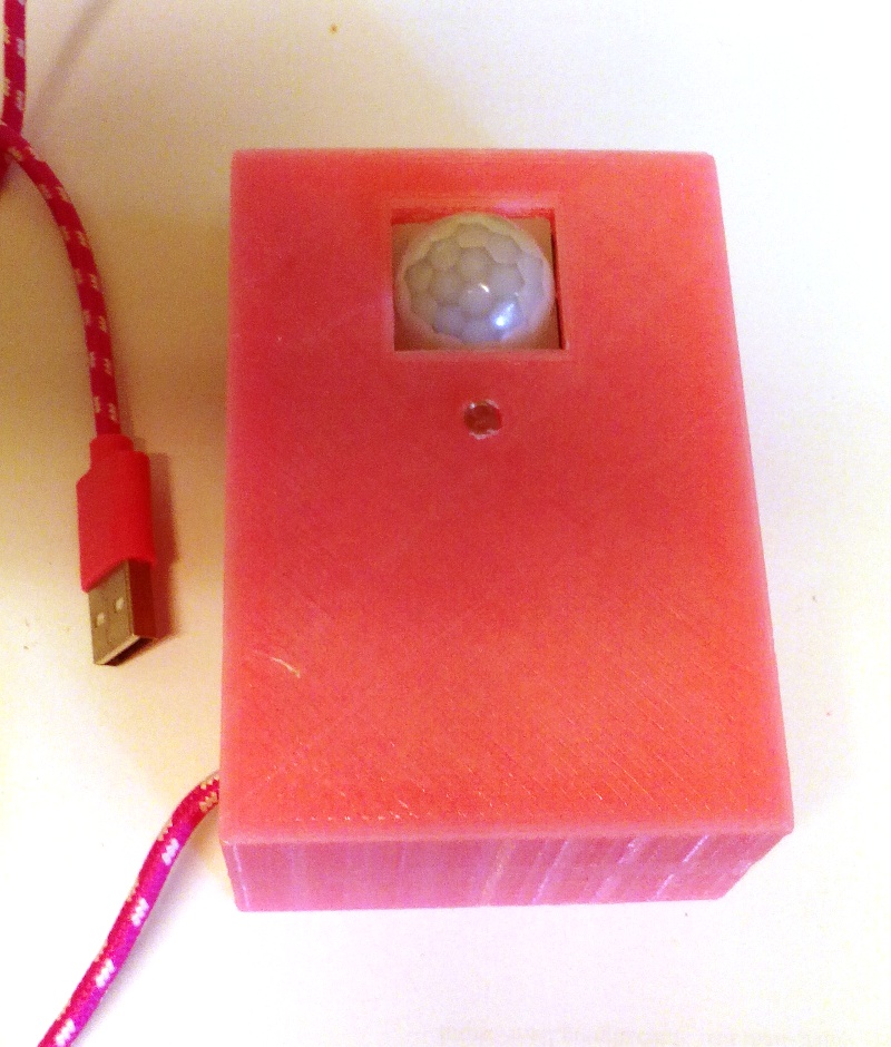
Every thing is set now. Above you can see my setup. I am looking for some kind of casing however I want it to be special. Like a womens head used in clothes-shops or a crystal ball or something like that.
The only thing you have to do is just say the Magic Words: OK Google
And wait a second.
Then say: Switch the living room light on
And the led should come on.
Just for fun look at the video demonstrating how it all comes together.
Ehhh and please do not comment on the mess.........
And just look at that. More fun coming up.
I connected Raspberry Home Assistant through IFTTT with my Domoticz system. So now I am not only able to connect to ESP's but also to commercial available lightning systems like Philips Hue or Klik-Aan-Klik-Uit and their cheap counterparts from the local dollar stores. These systems are commanded by a 433 Mhz frequency which is send by my domotica system that gets its commands from Raspberry Home Assistant. But that is a whole other story which I will save for a next time.
Till then.
Have fun
Luc Volders